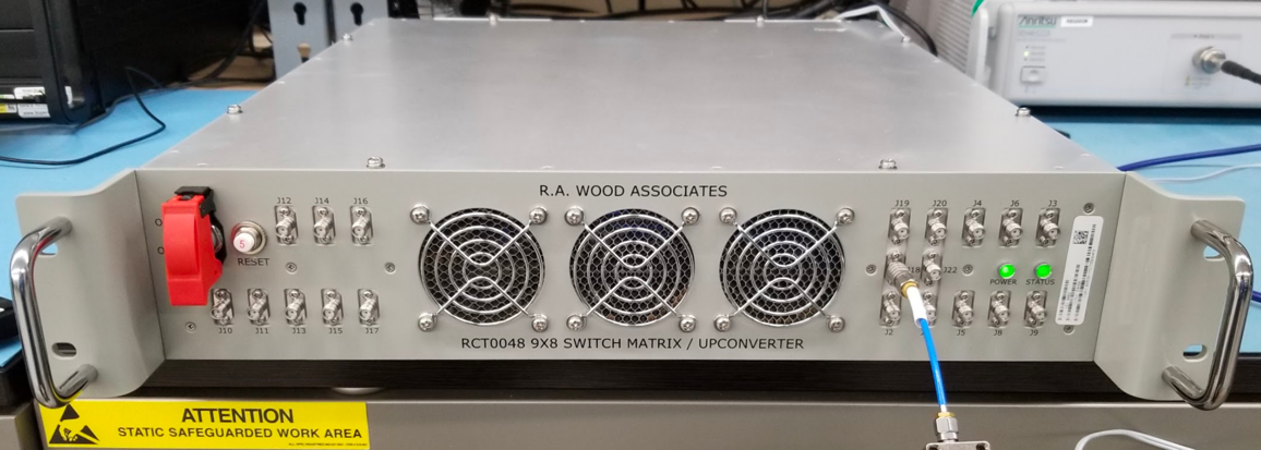
We've delivered our 40th 9X8 Switch Matrix / Up Converter. We designed and started producing these in 2018, and have made on-time deliveries on each one since then. Congrats to the team on getting these products completed on time!


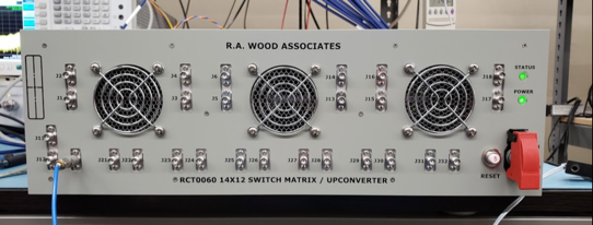
We just delivered SN022 of RCT0064. This unit allows 14 microwave inputs to be switched to any of 12 Microwave outputs. This was an extremely challenging design, with custom-designed 12-Way power dividers, our own RCT0050 WB Amplifiers, custom designed SP2T Switches, 3 internal switch matrix "cubes" (2X12, 6X12, and 6X12) with blind mate interconnections, and custom designed WB Digital Attenuator/Amplifiers, all in a 3U height rack mount package.

We've delivered Serial Number 25 of our 8X8 Switch Matrix / Up Converters, and are working on new orders of SN's 26-33. This is a 3U direct form, fit, and function replacement for a 6U LRU, giving the customer a modern upgrade and space savings at the same time. All deliveries have been on schedule!

We just delivered our 1st 14 X 12 Microwave Switch Matrix / Up Converter (RCT0060). This unit allows 14 microwave inputs to be switched to any of 12 Microwave outputs. This was an extremely challenging design, with custom designed 12-Way power dividers, our own RCT0050 WB Amplifiers, custom designed SP2T Switches, and custom designed WB Digital Attenuator/Amplifiers. The whole unit is made to fit in a 3U rack mount location. Congrats to our great mechanical and electrical design, and integration and test team for developing this successful design!

R. A. Wood Associates has received more orders for non-blocking microwave switch matrices for Naval applications. We have orders and are executing on QTY 21 9X8 Switch Matrices/Up Converters and QTY 20 8X8 Switch Matrices/Up Converters. Each of these matrices uses our own wideband power divider designs (8/9 each). The 9X8 design uses our own surface mount switches and ultra wideband (0.5 to 18 GHz) surface mount amplifier designs. Both of these products are packed into a 2U rack mount chassis design.

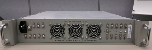
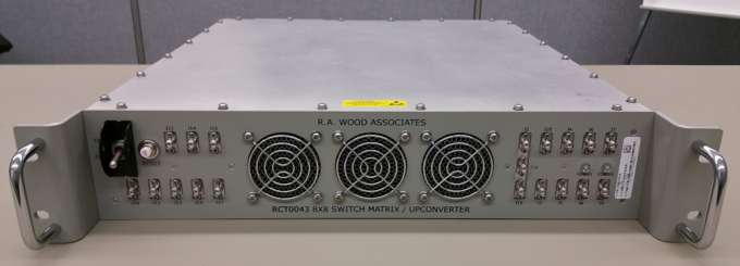
We just received an order for 9 RCT0043 Switch Matrix/Up Converters, to be used in Navy Vessels. These products allow 8 RF/microwave inputs to be routed to any of 8 RF/microwave output ports, The switch matrix is non-blocking. The design includes:
- Custom designed 8-way power dividers (covering a 4:1 bandwidth)
- A low band Up Converter
- An internal power supply
- High Speed LVDS interface
- High Dynamic Range RF amplifiers on inputs and outputs
- Custom designed equalizers for slope correction, and
- FPGA board for control and status (Built in Test) monitoring
The entire assembly is housed in a 2U rack mount assembly, saving precious rack space. The full frequency coverage is 0.5 to 18 GHz.

We delivered a new design to one of our customers: An 8X8 Microwave Switch Matrix /Up Converter. The unit allows 8 RF/microwave inputs to be routed to any of 8 RF/microwave output ports. The design includes:
- Custom designed 8-way power dividers (covering a 4:1 bandwidth)
- A low band Up Converter
- An AC/DC power supply
- High Speed LVDS interface
- High Dynamic Range RF amplifiers on inputs and outputs
- Custom designed equalizers for slope correction, and
- FPGA board for control and status (Built in Test) monitoring
The entire assembly is housed in a 2U rack mount assembly, saving precious rack space. The full frequency coverage is 0.5 to 18 GHz.
We received an order to design and build QTY 3 8X8 microwave switch matrices. The unit allows 8 RF/microwave inputs to be routed to any of 8 RF/microwave output ports. In another viewpoint, each of 8 RF/microwave output ports can select any of 8 RF/microwave input ports for down stream processing. The design includes:
- custom designed 8-way power dividers (covering a 4:1 bandwidth),
- a low band Up Converter,
- an AC/DC power supply,
- LVDS interface,
- RF amplifiers on inputs and outputs,
- custom design equalizers for slope correction,
- FPGA board for control and status (Built in Test) monitoring
The entire assembly is housed in a 2U rack mount assembly, saving precious rack space. The full frequency coverage is 0.5 to 18 GHz. The first unit will be delivered in September 2015.